Mesh
Terrain modelling is an important part of Septant. This modelisation has been done in order to manage different levels of detail, but also uses geomorphing to avoid gaps between the different levels of detail.
Using Heightmaps
We have already seen that terrain modeling is possible thanks to one or many heightmaps. A heightmap is a grayscale map of the terrain, where intensity of a pixel means the height of the point linked to that pixel.
Every single pixel of a map is linked to a vertex of the terrain. When using many heightmaps, those heightmaps are simply put one next to the other.
Patch structure
The terrains that we handle can have more than one million polygons. It is necessary to handle many levels of detail when modeling the terrain. Thus, a zone of the terrain that is near the camera will be more detailed than a zone that is far from the camera. To have a result that looks natural, we need coherence between the different patches.
To handle all these problems, we chose to use Greg Snook's method (see bibliography). It mainly deals about handling the continuity between patches thanks to precalculated patch patterns. We will assume that every patch has (2n+1)*(2n+1) vertices. Therefore, the terrain will be reduced in order to respect that constraint.
Different patch patterns
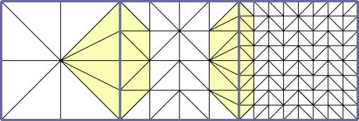
A patch is modeled from a pattern. A pattern is a list of indices that tells which vertices from the patch must be drawn. One level of detail is bound to a pattern.
Every pattern is made of nine elements:
- one body
- four normal edges
- four adaptatives edges


Notice that a pattern is just an array of indices, which are common to all patches, so its memory size is quite low.
Adaptation between different patches
We can have continuity between different patches thanks to adaptative edges. If a level n patch is close to a level n+1 patch, then the lower patch fits to the higher by using an adaptative edge on the side next to the n+1 level patch.

We can see now that our algorithm is slightly different from Greg Snook's one (the higher patch fits the lower one). Our modeling is more precise but a little bit slower when rendering.
Notice that this method has two constraints:
- you can't have more than one level of detail between two consecutive patches;
- the first level of detail is level one. It has one body and no edges.
Geomorphing
Problem and principle
Geomorphing solves the problem of rendering with LoD that we saw just before: the terrain moves suddenly when you change the level of detail. Thus, we need to smooth this move so that they will look less visible for the eye. Geomorphing deals about moving terrain vertices to change smoothly from one level of detail to another. Especially when changing from one LoD to a higher one: the odd
points must be moved to the elevation where they will have to be at the LoD changing.
Implementation
Implementation is divided in a few parts. First of all, we need to make a precalculation on the mesh to have the data that will be used when moving vertices. Then, a basic implementation has been done with a trivial
geomorphing. This implementation makes gaps appear again (as seen before) so we had to work further on that.

Pre-calculation of data
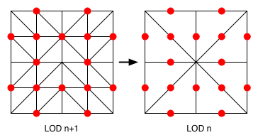
To make vertices transformation real-time, we need to know for each level of detail that has a lower level, how high is the center of every edge in each triangle from the mesh. Those points are painted in red above. For every one of these points, we calculate the average elevation between two vertices of each side, and we keep the LoD that we are processing.
This data is encoded in a normal array. We use one coordinate for the elevations, another one for the LoD of the elevation, and the third one for the real height of the point when the level of detail is the smoothest. That allows us not to change textures on zones that depend on the terrain's elevation.
Basic Implementation
To date, we used to calculate the level of detail with integer values to know what level has to be seen. For our implementation of the geomorphing, we musn't round that value. This will give us the integer part that will say what level of detail must be drawn, and a decimal part of the number between 0 and 1, saying how much we have to move the vertex to his final position.

Here, the adjusment rate is a. Every odd
vertex is adjusted from its position in the drawn level of detail. Then we add the difference between the starting position and the target position at the upper LoD multiplied by the coefficient a. And we need to pass the LoD of every patch as a float to find out which points have to be adjusted.
The adjustment is used when the level of detail of the processed patch is greater (by one) than the pre-calculated level of detail of the current point, that is to say when the current point is an odd
point.
However, this basic implementation leads to gap problems between patches. The reason is that two adjacent patches can't have the same level of detail and the same adjustment rate. The adjusted vertices on the edges of the patch are not adjusted in the same way, which makes the gap problem of joined patches appear again, as in the first implementations of the terrain.
Complete implementation
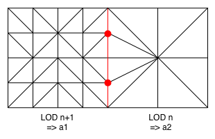
Due to that problem, we must make this implementation more complex in order to process the vertices on the sides of the patch. Therefore, we have decided that the adjustment of the right and down sides are done with the adjustment rate of that same patch whereas the two others use the adjustment rate of the left and upper sides. This guarantees that all the vertices will be adjusted in the same way. These different cases can be executed only on the four sides of the patches but not on the bodies.
The scheme shows which vertices meet these conditions in the cases of joined patches:

The vertex shader is modified for the vertices to be adjusted when the left or upper neighbour is adjustable and it has the same level of detail that the current patch, when the processed vertex is on a shared edge with the neighbour patch and the vertex is adjustable. The condition to make a patch adjustment is that the patch must have a level of detail greater or equal to 2. The condition to make a vertex adjustment is that the vertex has to be an odd
point.
Despite this, we can notice that this draft only handles the non-adjusted joined patches because it's not the same calculation for the adjusted joined patches (fot these ones, the neighbour has a level of detail greater by one). Thus, we need to process the vertices when the neighbour patch has a level of detail greater (by one) than the current patch, plus the already-seen-before conditions.
With those 5 conditions combined, it is now possible to handle all the cases without having two different adjustment rates for the same vertex. We still have a few mistakes due to rounded values that make pixel-sized gaps appear in some places. However, it allows us to have less problems than the gaps of the basic implementation, and it's hardly visible thanks to the environment.
In the next versions, we would like to see how to tranform the condition tests of geomorphing in a calculation method. In this method, the level of detail would be calculated for every vertex instead of every patch.
